
Page 113 - Finite Element Modeling and Simulations with ANSYS Workbench
P. 113
98 Finite Element Modeling and Simulation with ANSYS Workbench
In the Driving Dimensions folder showing up next, click on W1 to bring up its
default Ruler dimension value. Click on the default Ruler dimension value,
and change it to 0.1715m. Repeat the same steps for W2, W3, t1, t2, and t3,
and change the Ruler dimension values to 0.1715m for W2, 0.3556m for W3,
0.0073m for t1 and t2, and 0.0115m for t3. Close the SYS tab to return back to
the Graphics Window for sketch modeling.
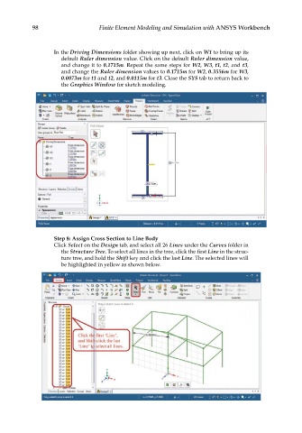
Step 8: Assign Cross Section to Line Body
Click Select on the Design tab, and select all 26 Lines under the Curves folder in
the Structure Tree. To select all lines in the tree, click the first Line in the struc-
ture tree, and hold the Shift key and click the last Line. The selected lines will
be highlighted in yellow as shown below.