
Page 214 - Finite Element Modeling and Simulations with ANSYS Workbench
P. 214
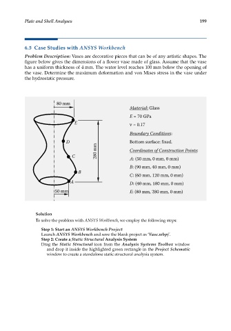
Plate and Shell Analyses                                                    199


            6.5  Case Studies with ANSYS Workbench
            Problem Description: Vases are decorative pieces that can be of any artistic shapes. The
            figure below gives the dimensions of a flower vase made of glass. Assume that the vase
            has a uniform thickness of 4 mm. The water level reaches 100 mm below the opening of
            the vase. Determine the maximum deformation and von Mises stress in the vase under
            the hydrostatic pressure.


                          80 mm
                                                          Material: Glass

                                                          E = 70 GPa
                                 E                         = 0.17

                                                          Boundary Conditions:
                              D                          Bottom surface: fixed.
                                           280 mm        Coordinates of Construction Points:

                                C                         A: (50 mm, 0 mm, 0 mm)

                                                          B: (90 mm, 40 mm, 0 mm)
                                   B
                                                         C: (60 mm, 120 mm, 0 mm)
                                A                         D: (40 mm, 180 mm, 0 mm)
                         50 mm                            E: (80 mm, 280 mm, 0 mm)


                 Solution
                 To solve the problem with ANSYS Workbench, we employ the following steps:

                   Step 1: Start an ANSYS Workbench Project
                   Launch ANSYS Workbench and save the blank project as ‘Vase.wbpj’.
                   Step 2: Create a Static Structural Analysis System
                   Drag the Static Structural icon from the  Analysis Systems Toolbox window
                     and drop it inside the highlighted green rectangle in the Project Schematic
                     window to create a standalone static structural analysis system.