
Page 213 - Finite Element Modeling and Simulations with ANSYS Workbench
P. 213
198 Finite Element Modeling and Simulation with ANSYS Workbench
+
Plane stress element Plate element
(membrane) (bending)
Flat shell element
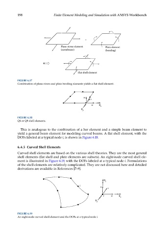
FIGURE 6.17
Combination of plane stress and plate bending elements yields a flat shell element.
w
v
u x
y
FIGURE 6.18
Q4 or Q8 shell elements.
This is analogous to the combination of a bar element and a simple beam element to
yield a general beam element for modeling curved beams. A flat shell element, with the
DOFs labeled at a typical node i, is shown in Figure 6.18.
6.4.5 Curved Shell Elements
Curved shell elements are based on the various shell theories. They are the most general
shell elements (flat shell and plate elements are subsets). An eight-node curved shell ele-
ment is illustrated in Figure 6.19, with the DOFs labeled at a typical node i. Formulations
of the shell elements are relatively complicated. They are not discussed here and detailed
derivations are available in References [7–9].
z
i
w v
i u x
y
FIGURE 6.19
An eight-node curved shell element and the DOFs at a typical node i.