
Page 209 - Finite Element Modeling and Simulations with ANSYS Workbench
P. 209
194 Finite Element Modeling and Simulation with ANSYS Workbench
p p
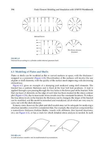
Internal forces:
p
p
Membrane stresses
dominate
FIGURE 6.9
Internal forces acting in a cylinder under internal pressure load.
6.3 Modeling of Plates and Shells
Plates or shells can be modeled as flat or curved surfaces in space, with the thickness t
assigned as a parameter (Figure 6.10). Discretization of the surfaces will involve the use
of plate or shell elements, with the quality of the surface mesh improving with decreasing
element size.
Figure 6.11 gives an example of a stamping part analyzed using shell elements. The
bracket has a uniform thickness and is fixed at the four bolt hole positions. A load is
applied through a pin passing through the two holes in the lower part of the bracket. Note
that one layer of elements on the edge of each hole has been masked in the stress contour
plot (Figure 6.11b), due to inaccurate stress results near the constraint locations. To reduce
the true stress levels in the bracket, the thickness can be changed, the shape of the bracket
can be modified, and the model is remeshed and reanalyzed, all of which are very easy to
carry out with the shell elements.
In many cases, however, the plate and shell models may not be adequate for analyzing a
structure member, even if it is considered thin. For example, the structure component has
a nonuniform thickness (turbine blades, vessels with stiffeners, thin layered structures,
etc.), see Figure 6.12, or has a crack for which detailed stress analysis is needed. In such
t
FIGURE 6.10
A shell structure member and its mathematical representation.