
Page 206 - Finite Element Modeling and Simulations with ANSYS Workbench
P. 206
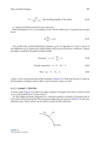
Plate and Shell Analyses                                                    191


                                    Et 3
                             D =        2   (the bending rigidity of the plate )       (6.12)
                                   (
                                  12 1 − ν  )
              q = lateral distributed load (force per unit area).
              Note that Equation 6.11 is of analogous form with the following 1-D equation for straight
            beam:


                                                 4
                                                dw
                                             EI     =  qx()                            (6.13)
                                                dx 4
              The fourth-order partial differential equation, given in Equation 6.11 and in terms of
            the deflection w(x,y), needs to be solved under certain given boundary conditions. Typical
            boundary conditions for plate bending include:


                                                         ∂ w
                                       Clamped: w = 0,       = 0                       (6.14)
                                                          ∂ n

                                   Simply supported: w = 0,  M n = 0                   (6.15)


                                         Free: Q n = 0,  M n = 0                       (6.16)


            where n is the normal direction of the boundary (Figure 6.5). Note that the given values in
            the boundary conditions shown above can be nonzero values as well.


            6.2.2.1  Example: A Thin Plate
            A square plate (Figure 6.6) with four edges clamped or hinged, and under a uniform load
            q or a concentrated force P at the center C.
              For this simple geometry, Equation 6.11 with the boundary condition of Equation 6.14 or
            6.15 can be solved analytically. The maximum deflections are given in Table 6.1 for the four
            different cases. These values can be used to verify the FEA solutions.


                                            s          n


                                                        Boundary

            FIGURE 6.5
            The boundary of a plate.