
Page 208 - Finite Element Modeling and Simulations with ANSYS Workbench
P. 208
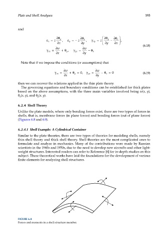
Plate and Shell Analyses 193
and
∂θ
ε= z ∂θ y , ε= − z ∂θ x , γ xy = z ∂θ y − x ,
y
x
x
∂x ∂y ∂y ∂
(6.18)
∂w ∂w
γ xz = +θ y , γ yz = −θ x
z
∂x ∂ y
Note that if we impose the conditions (or assumptions) that
∂w ∂w
= +θ = 0, = −θ = 0 (6.19)
γ xz y γ yz x
∂x ∂y
then we can recover the relations applied in the thin plate theory.
The governing equations and boundary conditions can be established for thick plates
based on the above assumptions, with the three main variables involved being w(x, y),
θ (x, y), and θ (x, y).
y
x
6.2.4 Shell Theory
Unlike the plate models, where only bending forces exist, there are two types of forces in
shells, that is, membrane forces (in plane forces) and bending forces (out of plane forces)
(Figures 6.8 and 6.9).
6.2.4.1 Shell Example: A Cylindrical Container
Similar to the plate theories, there are two types of theories for modeling shells, namely
thin shell theory and thick shell theory. Shell theories are the most complicated ones to
formulate and analyze in mechanics. Many of the contributions were made by Russian
scientists in the 1940s and 1950s, due to the need to develop new aircrafts and other light-
weight structures. Interested readers can refer to Reference [6] for in-depth studies on this
subject. These theoretical works have laid the foundations for the development of various
finite elements for analyzing shell structures.
FIGURE 6.8
Forces and moments in a shell structure member.