
Page 211 - Finite Element Modeling and Simulations with ANSYS Workbench
P. 211
196 Finite Element Modeling and Simulation with ANSYS Workbench
z y
Mid-surface 4 3
x
1 2
w w t w w
w , , w , ,
1 x 1 y 1 2 x 2 y 2
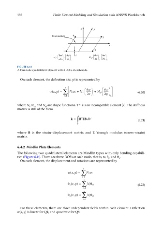
FIGURE 6.13
A four-node quadrilateral element with 3 DOFs at each node.
On each element, the deflection w(x, y) is represented by
4
w(, ) = ∑ Nw i + N xi ∂ ∂ w + N yi ∂ ∂ w (6.20)
xy
i
x
i
i=1 i y
where N, N , and N are shape functions. This is an incompatible element [7]. The stiffness
i
xi
yi
matrix is still of the form
k = ∫ B EB dV (6.21)
T
V
where B is the strain–displacement matrix and E Young’s modulus (stress–strain)
matrix.
6.4.2 Mindlin Plate Elements
The following two quadrilateral elements are Mindlin types with only bending capabili-
ties (Figure 6.14). There are three DOFs at each node, that is, w, θ , and θ .
x
y
On each element, the displacement and rotations are represented by
n
wx y) = ∑ N w i
(,
i
i=1 n
θ x (, ∑ N i θ xi (6.22)
xy) =
i=1
n
xy) =
θ y (, ∑ N i θ yi
i=1
For these elements, there are three independent fields within each element. Deflection
w(x, y) is linear for Q4, and quadratic for Q8.