
Page 207 - Finite Element Modeling and Simulations with ANSYS Workbench
P. 207
192 Finite Element Modeling and Simulation with ANSYS Workbench
z
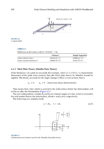
Given: E, t, and = 0.3
y
C
L
x L
FIGURE 6.6
A square plate.
TABLE 6.1
2
3
Deflection at the Center (with D = Et /(12(1 − v )))
Clamped Simply Supported
Under uniform load q 0.00126 qL /D 0.00406 qL /D
4
4
Under concentrated force P 0.00560 PL /D 0.0116 PL /D
2
2
6.2.3 Thick Plate Theory (Mindlin Plate Theory)
If the thickness t of a plate is not small, for example, when t/L ≥ 1/10 (L = a characteristic
dimension of the plate main surface), then the thick plate theory by Mindlin should be
applied. The theory accounts for the angle changes within a cross section, that is
γ xz ≠ 0, γ yz ≠ 0 (transverse shear deformations )
This means that a line which is normal to the mid-surface before the deformation will
not be so after the deformation (Figure 6.7).
The new independent variables θ and θ are rotation angles of a line, which is normal to
x
y
the mid-surface before the deformation, about x- and y-axis, respectively.
The following new relations hold:
z
u =θ , v =− θ (6.17)
y z x
w
z y –
x
w
w x
x
FIGURE 6.7
Displacement and rotation based on the Mindlin thick plate theory.