
Page 210 - Finite Element Modeling and Simulations with ANSYS Workbench
P. 210
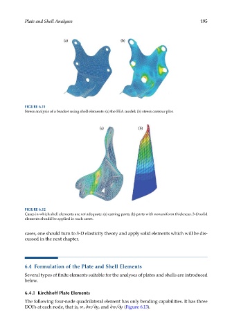
Plate and Shell Analyses                                                    195


            FIGURE 6.11
            Stress analysis of a bracket using shell elements: (a) the FEA model; (b) stress contour plot.


            FIGURE 6.12
            Cases in which shell elements are not adequate: (a) casting parts; (b) parts with nonuniform thickness. 3-D solid
            elements should be applied in such cases.


            cases, one should turn to 3-D elasticity theory and apply solid elements which will be dis-
            cussed in the next chapter.


            6.4  Formulation of the Plate and Shell Elements

            Several types of finite elements suitable for the analyses of plates and shells are introduced
            below.

            6.4.1  Kirchhoff Plate Elements

            The following four-node quadrilateral element has only bending capabilities. It has three
                                                    ∂
            DOFs at each node, that is, w, ∂ w ∂ y, and ∂wy/  (Figure 6.13).
                                         /