
Page 204 - Finite Element Modeling and Simulations with ANSYS Workbench
P. 204
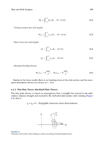
Plate and Shell Analyses                                                    189


                                       M y = ∫ t/2  σ y  zdz,( Nm m)                   (6.2)
                                                          ⋅
                                                             /
                                              t − /2
              Twisting moment (per unit length):


                                                           ⋅
                                      M xy = ∫ t/2  τ xy zdz,( Nm m)                   (6.3)
                                                             /
                                              t − /2
              Shear Forces (per unit length):


                                         Q x = ∫ t/2  τ xz  dz,( N m)                  (6.4)
                                                           /
                                               t − /2

                                        Q y = ∫ t/2  τ yz  dz,( N m)                   (6.5)
                                                           /
                                               t − /2

              Maximum bending stresses:

                                              6 M              6 M
                                       ) max = ±  x    ) max =±   y                    (6.6)
                                    (σ x        2  ,(σ y         2
                                               t                t

              Similar to the beam model, there is no bending stress at the mid-surface and the maxi-
            mum/minimum stresses are always at z = ±t/2.


            6.2.2  Thin Plate Theory (Kirchhoff Plate Theory)

            The thin plate theory is based on assumptions that a straight line normal to the mid-
            surface remains straight and normal to the deflected mid-surface after loading (Figure
            6.4); that is

                           γ  = γ  = 0  (Negligible transverse shear deformations)
                                yz
                            xz


                                                       w
                                        z               x


                                                             w
                                                                x


            FIGURE 6.4
            Deflection and rotation after loading of a plate according to Kirchhoff plate theory.