
Page 248 - Finite Element Modeling and Simulations with ANSYS Workbench
P. 248
Three-Dimensional Elasticity 233
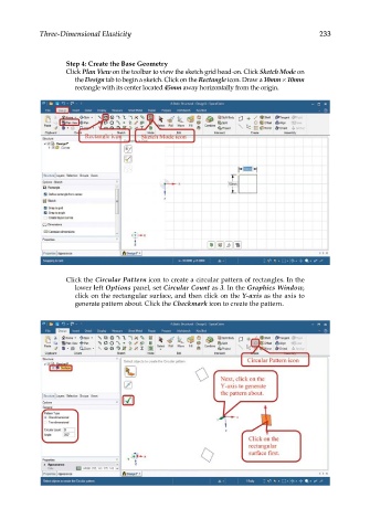
Step 4: Create the Base Geometry
Click Plan View on the toolbar to view the sketch grid head-on. Click Sketch Mode on
the Design tab to begin a sketch. Click on the Rectangle icon. Draw a 10mm × 10mm
rectangle with its center located 45mm away horizontally from the origin.
Click the Circular Pattern icon to create a circular pattern of rectangles. In the
lower left Options panel, set Circular Count as 3. In the Graphics Window,
click on the rectangular surface, and then click on the Y-axis as the axis to
generate pattern about. Click the Checkmark icon to create the pattern.