
Page 245 - Finite Element Modeling and Simulations with ANSYS Workbench
P. 245
230 Finite Element Modeling and Simulation with ANSYS Workbench
pA/3 pA/12
p
Surface area = A Nodal forces for 20-node
brick element
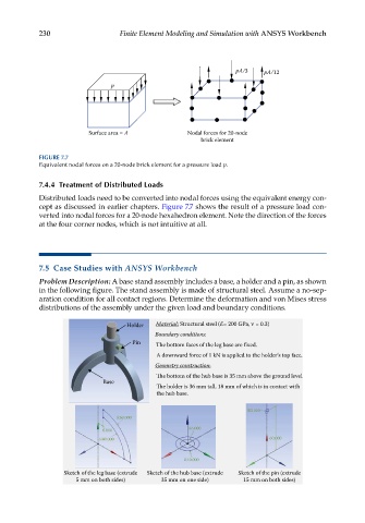
FIGURE 7.7
Equivalent nodal forces on a 20-node brick element for a pressure load p.
7.4.4 Treatment of Distributed Loads
Distributed loads need to be converted into nodal forces using the equivalent energy con-
cept as discussed in earlier chapters. Figure 7.7 shows the result of a pressure load con-
verted into nodal forces for a 20-node hexahedron element. Note the direction of the forces
at the four corner nodes, which is not intuitive at all.
7.5 Case Studies with ANSYS Workbench
Problem Description: A base stand assembly includes a base, a holder and a pin, as shown
in the following figure. The stand assembly is made of structural steel. Assume a no-sep-
aration condition for all contact regions. Determine the deformation and von Mises stress
distributions of the assembly under the given load and boundary conditions.
Holder Material: Structural steel (E= 200 GPa, = 0.3)
Boundary conditions:
Pin The bottom faces of the leg base are fixed.
A downward force of 1 kN is applied to the holder’s top face.
Geometry construction:
e bottom of the hub base is 35 mm above the ground level.
Base
e holder is 36 mm tall, 18 mm of which is in contact with
the hub base.
R3.000
R50.000
R6.000
8.000
R40.000 60.000
R10.000
Sketch of the leg base (extrude Sketch of the hub base (extrude Sketch of the pin (extrude
5 mm on both sides) 35 mm on one side) 15 mm on both sides)