
Page 241 - Finite Element Modeling and Simulations with ANSYS Workbench
P. 241
226 Finite Element Modeling and Simulation with ANSYS Workbench
Or in a matrix form:
u = N d
Using relations given in Equations 7.5 and 7.8, we can derive the strain vector to obtain:
ε = B d
in which B is the matrix relating the nodal displacement vector d to the strain vector ε.
Note that the dimensions of the B matrix are 6 × 3N.
Once the B matrix is found, one can apply the following familiar expression to deter-
mine the stiffness matrix for the element:
k = ∫ B EBdv (7.10)
T
v
The dimensions of the stiffness matrix k are 3N × 3N. A numerical quadrature is often
needed to evaluate the above integration, which can be expensive if the number of nodes
is large, such as for higher-order elements.
7.4.2 Typical Solid Element Types
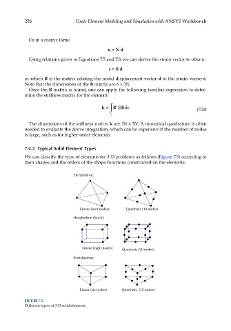
We can classify the type of elements for 3-D problems as follows (Figure 7.5) according to
their shapes and the orders of the shape functions constructed on the elements:
Tetrahedron:
Linear (four nodes) Quadratic (10 nodes)
Hexahedron (brick):
Linear (eight nodes) Quadratic (20 nodes)
Pentahedron:
Linear (six nodes) Quadratic (15 nodes)
FIGURE 7.5
Different types of 3-D solid elements.