
Page 237 - Finite Element Modeling and Simulations with ANSYS Workbench
P. 237
222 Finite Element Modeling and Simulation with ANSYS Workbench
p
n
(= + )
u
u
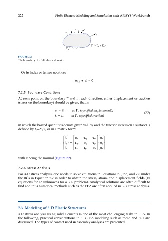
FIGURE 7.2
The boundary of a 3-D elastic domain.
Or in index or tensor notation:
σ ij j, + i f = 0
7.2.5 Boundary Conditions
At each point on the boundary Γ and in each direction, either displacement or traction
(stress on the boundary) should be given, that is
u i = u i , on Γ u ( specifieddisplacement); (7.7)
t i = t i , on Γ ( specifiedtracttion)
σ
in which the barred quantities denote given values, and the traction (stress on a surface) is
defined by t i =σ n j or in a matrix form:
ij
t x x σ τ xy τ xz n x
t y = τ xy σ y τ yz n y
τ τ σ
t z xz yz z n z
with n being the normal (Figure 7.2).
7.2.6 Stress Analysis
For 3-D stress analysis, one needs to solve equations in Equations 7.3, 7.5, and 7.6 under
the BCs in Equation 7.7 in order to obtain the stress, strain, and displacement fields (15
equations for 15 unknowns for a 3-D problem). Analytical solutions are often difficult to
find and thus numerical methods such as the FEA are often applied in 3-D stress analysis.
7.3 Modeling of 3-D Elastic Structures
3-D stress analysis using solid elements is one of the most challenging tasks in FEA. In
the following, practical considerations in 3-D FEA modeling such as mesh and BCs are
discussed. The types of contact used in assembly analyses are presented.