
Page 238 - Finite Element Modeling and Simulations with ANSYS Workbench
P. 238
Three-Dimensional Elasticity 223
7.3.1 Mesh Discretization
Meshing structures with complicated geometries can be very tedious and time-
consuming. Great care should be taken to ensure that the FEA mesh is in good quality
(e.g., with no distorted elements). Computing cost is another factor. For structures with
stress concentrations, large FEA models are often needed, which can run hours or days. A
good CAE engineer should be able to decide where to apply a fine mesh and where not to,
in order to strike a balance between the computational cost and accuracy for an FEA task.
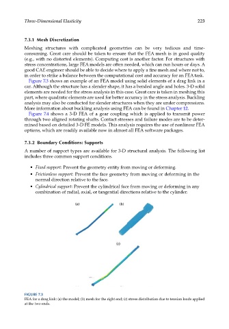
Figure 7.3 shows an example of an FEA model using solid elements of a drag link in a
car. Although the structure has a slender shape, it has a bended angle and holes. 3-D solid
elements are needed for the stress analysis in this case. Great care is taken in meshing this
part, where quadratic elements are used for better accuracy in the stress analysis. Buckling
analysis may also be conducted for slender structures when they are under compressions.
More information about buckling analysis using FEA can be found in Chapter 12.
Figure 7.4 shows a 3-D FEA of a gear coupling which is applied to transmit power
through two aligned rotating shafts. Contact stresses and failure modes are to be deter-
mined based on detailed 3-D FE models. This analysis requires the use of nonlinear FEA
options, which are readily available now in almost all FEA software packages.
7.3.2 Boundary Conditions: Supports
A number of support types are available for 3-D structural analysis. The following list
includes three common support conditions.
• Fixed support: Prevent the geometry entity from moving or deforming.
• Frictionless support: Prevent the face geometry from moving or deforming in the
normal direction relative to the face.
• Cylindrical support: Prevent the cylindrical face from moving or deforming in any
combination of radial, axial, or tangential directions relative to the cylinder.
FIGURE 7.3
FEA for a drag link: (a) the model; (b) mesh for the right end; (c) stress distribution due to tension loads applied
at the two ends.