
Page 239 - Finite Element Modeling and Simulations with ANSYS Workbench
P. 239
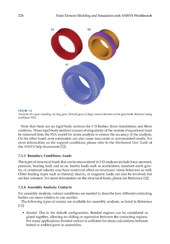
224                   Finite Element Modeling and Simulation with ANSYS Workbench


            FIGURE 7.4
            Analysis of a gear coupling: (a) ring gear; (b) hub gear; (c) high-contact stresses in the gear teeth obtained using
            nonlinear FEA.

              Note that there are six rigid-body motions for 3-D bodies: three translations and three
            rotations. These rigid-body motions (causes of singularity of the system of equations) must
            be removed from the FEA model for stress analysis to ensure the accuracy of the analysis.
            On the other hand, over constraints can also cause inaccurate or unwarranted results. For
            more information on the support conditions, please refer to the Mechanical User Guide of
            the ANSYS help documents [12].


            7.3.3  Boundary Conditions: Loads
            The types of structural loads that can be encountered in 3-D analyses include force, moment,
            pressure, bearing load, and so on. Inertia loads such as acceleration, standard earth grav-
            ity, or rotational velocity may have nontrivial effect on structures’ stress behaviors as well.
            Other loading types such as thermal, electric, or magnetic loads can also be involved, but
            are less common. For more information on the structural loads, please see Reference [12].

            7.3.4  Assembly Analysis: Contacts

            For assembly analysis, contact conditions are needed to describe how different contacting
            bodies can move relative to one another.
              The following types of contact are available for assembly analysis, as listed in Reference
            [12]:

              •  Bonded: This is the default configuration. Bonded regions can be considered as
                 glued together, allowing no sliding or separation between the contacting regions.
                 For many applications, bonded contact is sufficient for stress calculations between
                 bolted or welded parts in assemblies.