
Page 274 - Finite Element Modeling and Simulations with ANSYS Workbench
P. 274
Three-Dimensional Elasticity 259
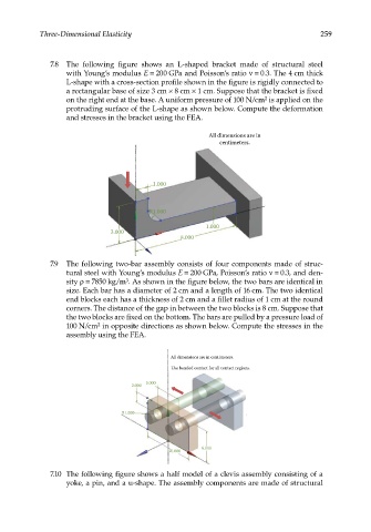
7.8 The following figure shows an L-shaped bracket made of structural steel
with Young’s modulus E = 200 GPa and Poisson’s ratio ν = 0.3. The 4 cm thick
L-shape with a cross-section profile shown in the figure is rigidly connected to
a rectangular base of size 3 cm × 8 cm × 1 cm. Suppose that the bracket is fixed
on the right end at the base. A uniform pressure of 100 N/cm is applied on the
2
protruding surface of the L-shape as shown below. Compute the deformation
and stresses in the bracket using the FEA.
All dimensions are in
centimeters.
1.000
R1.000
1.000
3.000
8.000
7.9 The following two-bar assembly consists of four components made of struc-
tural steel with Young’s modulus E = 200 GPa, Poisson’s ratio ν = 0.3, and den-
sity ρ = 7850 kg/m . As shown in the figure below, the two bars are identical in
3
size. Each bar has a diameter of 2 cm and a length of 16 cm. The two identical
end blocks each has a thickness of 2 cm and a fillet radius of 1 cm at the round
corners. The distance of the gap in between the two blocks is 8 cm. Suppose that
the two blocks are fixed on the bottom. The bars are pulled by a pressure load of
100 N/cm in opposite directions as shown below. Compute the stresses in the
2
assembly using the FEA.
All dimensions are in centimeter
All dimensions are in centimeterss.
Use bonded contact for all contact regions.
Use bonded contact for all contact region s.
5.000
5.000
2.000
2.000
R1.000
R1.000
6.000
6.000
10.000
10.000
7.10 The following figure shows a half model of a clevis assembly consisting of a
yoke, a pin, and a u-shape. The assembly components are made of structural