
Page 277 - Finite Element Modeling and Simulations with ANSYS Workbench
P. 277
262 Finite Element Modeling and Simulation with ANSYS Workbench
f(t)
FIGURE 8.1
A dynamic force applied to the structure.
k f = f(t)
m m—mass
c k—stiffness
c—damping
f(t)—force
FBD: ku m f(t)
cu
x, u
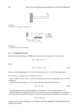
FIGURE 8.2
A single DOF system with damping.
8.2.1 A Single DOF System
From the free-body diagram (FBD) and Newton’s law of motion (ma = f), we have:
ft −
mu = () ku − cu
that is
mu + cu + ku = ft() (8.1)
/
2
where u is the displacement, u = dudt the velocity, and u = d udt the acceleration.
2
/
Free Vibration (no applied force to the mass or f(t) = 0):
Free vibration occurs when a mass is moved away from its rest position due to initial
conditions.
Assuming zero damping (c = 0) in a free vibration, Equation 8.1 becomes:
mu + ku = 0 (8.2)
The physical meaning of this equation is: inertia force + elastic/stiffness force = 0.
Although there is no applied force, the mass can have nonzero displacement or experience
vibrations under the initial conditions. To solve for such nontrivial solutions, we assume:
u(t) = U sin ωt
where ω is the circular frequency of oscillation and U the amplitude. Substituting this into
Equation 8.2 yields: