
Page 281 - Finite Element Modeling and Simulations with ANSYS Workbench
P. 281
266 Finite Element Modeling and Simulation with ANSYS Workbench
v 1 v 2
1 , A, L 2
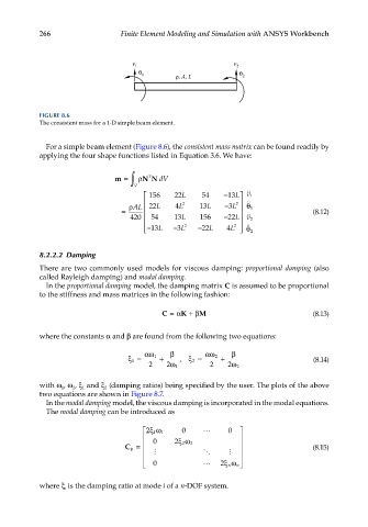
FIGURE 8.6
The consistent mass for a 1-D simple beam element.
For a simple beam element (Figure 8.6), the consistent mass matrix can be found readily by
applying the four shape functions listed in Equation 3.6. We have:
m = ∫ V ρ N N dV
T
156 22 L 54 −13 L 1 v
ρAL 22 L 4 L 2 13 L − L 2 1 θ
3
= (8.12)
420 54 13 L 156 −22 2
L v
2 2
3
−13L − 3L − 22L 4L 2 θ
8.2.2.2 Damping
There are two commonly used models for viscous damping: proportional damping (also
called Rayleigh damping) and modal damping.
In the proportional damping model, the damping matrix C is assumed to be proportional
to the stiffness and mass matrices in the following fashion:
C =α K +β M (8.13)
where the constants α and β are found from the following two equations:
αω β α ω 2 β
ξ= 1 + , ξ= + (8.14)
1
2
2 2 ω 1 2 2 ω 2
with ω , ω , ξ and ξ (damping ratios) being specified by the user. The plots of the above
1
1
2
2
two equations are shown in Figure 8.7.
In the modal damping model, the viscous damping is incorporated in the modal equations.
The modal damping can be introduced as
0 0
ξω 1
2 1
0
ξω 2
C φ = 2 2 (8.15)
0
ξω n
2 n
where ξ is the damping ratio at mode i of a n-DOF system.
i