Page 324 - Finite Element Modeling and Simulations with ANSYS Workbench
P. 324

Thermal Analysis                                                            309
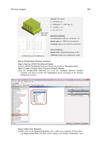


                                                   Material: Aluminum
                                                   k = 170 W/(m·K)
                                                             3
                                                   ρ = 2800 kg/m ; c = 870 J/(kg· K)
                                                   E = 70 GPa; ν = 0.3
                                                   α = 22×10 –6  1/°C
                                          Base of the
                                          heat sink   Boundary Conditions:
                                                                             2
                                                   Air temperature of 28°C; h = 30 W/(m ·°C).
                                                                       2

                                                   Steady-state: q' = 1000 W/m on the base.
                                                   Transient: Square wave heat flux on the base.
                                                   Initial Conditions:
                                                   Steady-state: Uniform temperature of 28°C.
                       All dimensions are in millimeters.  Transient: Steady-state temperature results.

                   Part A: Steady-State Thermal Analysis
                   Step 1: Start an ANSYS Workbench Project
                   Launch ANSYS Workbench and save the blank project as ‘Heatsink.wbpj’.
                   Step 2: Create a Steady-State Thermal Analysis System
                   Drag the  Steady-State Thermal icon from the  Analysis Systems Toolbox
                     window and drop it inside the highlighted green rectangle in the  Project
                     Schematic window.


                   Step 3: Add a New Material
                   Double-click on the Engineering Data cell to add a new material. In the follow-
                     ing Engineering Data interface which replaces the Project Schematic, type
   319   320   321   322   323   324   325   326   327   328   329