
Page 319 - Finite Element Modeling and Simulations with ANSYS Workbench
P. 319
304 Finite Element Modeling and Simulation with ANSYS Workbench
9.2.2.1 1-D Case
To understand the stress–strain relations in cases where solids undergo temperature
changes, we first examine the 1-D case (Figure 9.3). We have for the thermal strain (or
initial strain):
ε = αΔT (9.10)
o
in which
α = the coefficient of thermal expansion
ΔT = T − T = change of temperature
2
1
Total strain is given by
ε = ε + ε o (9.11)
e
with ε being the elastic strain due to mechanical load.
e
That is, the total strain can be written as
ε = E σ + αΔT (9.12)
−1
Or, inversely, the stress is given by
σ = E(ε – ε ) (9.13)
o
EXAMPLE 9.1
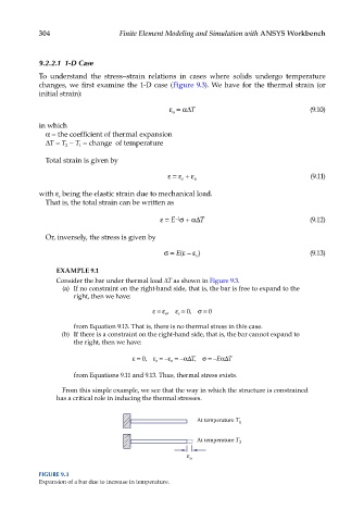
Consider the bar under thermal load ΔT as shown in Figure 9.3.
(a) If no constraint on the right-hand side, that is, the bar is free to expand to the
right, then we have:
ε = ε o , ε e = 0, σ = 0
from Equation 9.13. That is, there is no thermal stress in this case.
(b) If there is a constraint on the right-hand side, that is, the bar cannot expand to
the right, then we have:
ε = 0, ε e = −ε o = −αΔT, σ = −EαΔT
from Equations 9.11 and 9.13. Thus, thermal stress exists.
From this simple example, we see that the way in which the structure is constrained
has a critical role in inducing the thermal stresses.
At temperature T 1
At temperature T 2
o
FIGURE 9.3
Expansion of a bar due to increase in temperature.