
Page 323 - Finite Element Modeling and Simulations with ANSYS Workbench
P. 323
308 Finite Element Modeling and Simulation with ANSYS Workbench
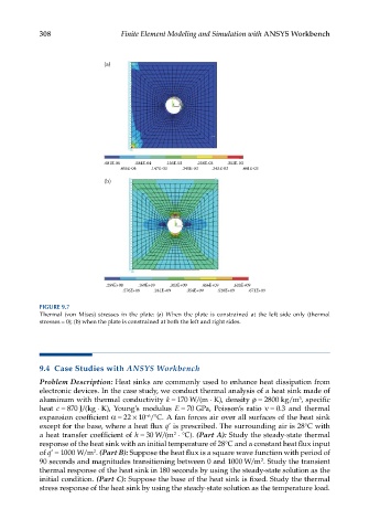
(a)
.681E-06 .584E-04 .156E-03 .258E-03 .352E-03
.456E-04 .147E-03 .245E-03 .343E-03 .441E-03
(b)
.259E+08 .169E+09 .313E+09 .456E+09 .600E+09
.576E+08 .241E+09 .354E+09 .528E+09 .671E+09
FIGURE 9.7
Thermal (von Mises) stresses in the plate: (a) When the plate is constrained at the left side only (thermal
stresses = 0); (b) when the plate is constrained at both the left and right sides.
9.4 Case Studies with ANSYS Workbench
Problem Description: Heat sinks are commonly used to enhance heat dissipation from
electronic devices. In the case study, we conduct thermal analysis of a heat sink made of
3
aluminum with thermal conductivity k = 170 W/(m ⋅ K), density ρ = 2800 kg/m , specific
heat c = 870 J/(kg ⋅ K), Young’s modulus E = 70 GPa, Poisson’s ratio ν = 0.3 and thermal
−6
expansion coefficient α = 22 × 10 /°C. A fan forces air over all surfaces of the heat sink
except for the base, where a heat flux q’ is prescribed. The surrounding air is 28°C with
a heat transfer coefficient of h = 30 W/(m ⋅ °C). (Part A): Study the steady-state thermal
2
response of the heat sink with an initial temperature of 28°C and a constant heat flux input
of q’ = 1000 W/m . (Part B): Suppose the heat flux is a square wave function with period of
2
2
90 seconds and magnitudes transitioning between 0 and 1000 W/m . Study the transient
thermal response of the heat sink in 180 seconds by using the steady-state solution as the
initial condition. (Part C): Suppose the base of the heat sink is fixed. Study the thermal
stress response of the heat sink by using the steady-state solution as the temperature load.