
Page 347 - Finite Element Modeling and Simulations with ANSYS Workbench
P. 347
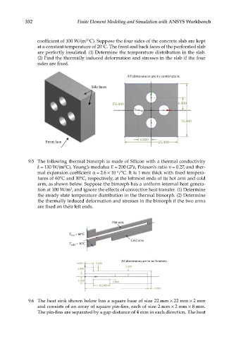
332                   Finite Element Modeling and Simulation with ANSYS Workbench


                 coefficient of 100 W/(m °C). Suppose the four sides of the concrete slab are kept
                                      2
                 at a constant temperature of 20°C. The front and back faces of the perforated slab
                 are perfectly insulated. (1) Determine the temperature distribution in the slab.
                 (2) Find the thermally induced deformation and stresses in the slab if the four
                 sides are fixed.


                                                       All dimensions are in centimeters.
                                        Side faces


                                                 D5.000                      6.000


                                                                              25.000


                                                             6.000
                    Front face                                       25.000


              9.5  The following thermal bimorph is made of Silicon with a thermal conductivity
                 k = 130 W/(m°C), Young’s modulus E = 200 GPa, Poisson’s ratio ν = 0.27, and ther-
                                                  −6
                 mal expansion coefficient α = 2.6 × 10 /°C. It is 1 mm thick with fixed tempera-
                 tures of 60°C and 10°C, respectively, at the leftmost ends of its hot arm and cold
                 arm, as shown below. Suppose the bimorph has a uniform internal heat genera-
                               3
                 tion at 100 W/m , and ignore the effects of convective heat transfer. (1) Determine
                 the steady-state temperature distribution in the thermal bimorph. (2) Determine
                 the thermally induced deformation and stresses in the bimorph if the two arms
                 are fixed on their left ends.


                                                 Hot arm


                              T   = 60°C
                               hot
                                                         Cold arm
                              T cold  = 10°C


                                                     All dimensions are in millimeters.
                                  6.000   3.000
                                                       2.000
                                  2.000
                                  5.000          2.000
                                            12.000
                                                                   3.000

              9.6  The heat sink shown below has a square base of size 22 mm × 22 mm × 2 mm
                 and consists of an array of square pin-fins, each of size 2 mm × 2 mm × 8 mm.
                 The pin-fins are separated by a gap distance of 4 mm in each direction. The heat