
Page 220 - Flexible Robotics in Medicine
P. 220
Compliant bending tubular mechanisms with variable groove patterns 207
Figure 8.12
3D models of different sections. (A) Top section, (B) middle section, and (C) bottom section.
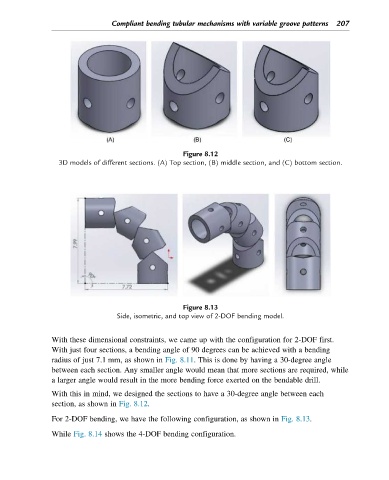
Figure 8.13
Side, isometric, and top view of 2-DOF bending model.
With these dimensional constraints, we came up with the configuration for 2-DOF first.
With just four sections, a bending angle of 90 degrees can be achieved with a bending
radius of just 7.1 mm, as shown in Fig. 8.11. This is done by having a 30-degree angle
between each section. Any smaller angle would mean that more sections are required, while
a larger angle would result in the more bending force exerted on the bendable drill.
With this in mind, we designed the sections to have a 30-degree angle between each
section, as shown in Fig. 8.12.
For 2-DOF bending, we have the following configuration, as shown in Fig. 8.13.
While Fig. 8.14 shows the 4-DOF bending configuration.