
Page 216 - Flexible Robotics in Medicine
P. 216
Compliant bending tubular mechanisms with variable groove patterns 203
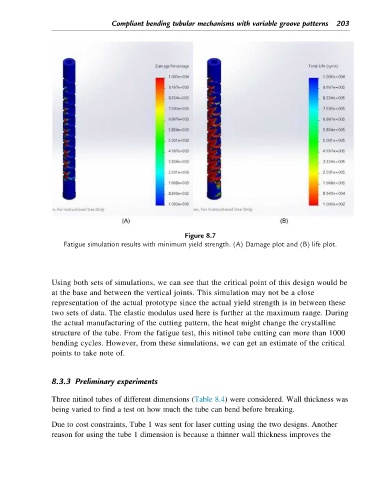
Figure 8.7
Fatigue simulation results with minimum yield strength. (A) Damage plot and (B) life plot.
Using both sets of simulations, we can see that the critical point of this design would be
at the base and between the vertical joints. This simulation may not be a close
representation of the actual prototype since the actual yield strength is in between these
two sets of data. The elastic modulus used here is further at the maximum range. During
the actual manufacturing of the cutting pattern, the heat might change the crystalline
structure of the tube. From the fatigue test, this nitinol tube cutting can more than 1000
bending cycles. However, from these simulations, we can get an estimate of the critical
points to take note of.
8.3.3 Preliminary experiments
Three nitinol tubes of different dimensions (Table 8.4) were considered. Wall thickness was
being varied to find a test on how much the tube can bend before breaking.
Due to cost constraints, Tube 1 was sent for laser cutting using the two designs. Another
reason for using the tube 1 dimension is because a thinner wall thickness improves the