
Page 349 - Flexible Robotics in Medicine
P. 349
340 Chapter 14
Figure 14.12
Inner concentric tube with mounted FBGs.
Multithreaded python program
Readings Coordinate
Forces Kinematic
Computer
Input model
Calibration matrix
Actuator input
Optical Motor
interrogator drivers
Wavelength shift Position
FBG sensors CTR
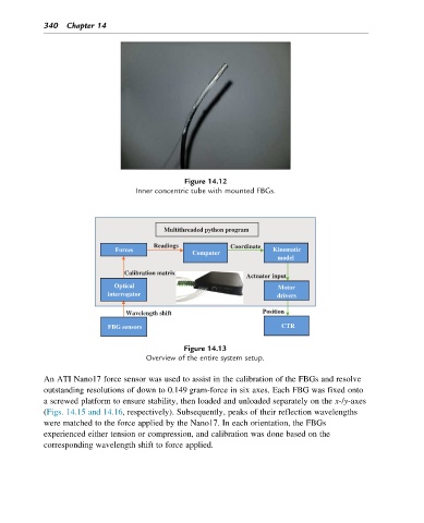
Figure 14.13
Overview of the entire system setup.
An ATI Nano17 force sensor was used to assist in the calibration of the FBGs and resolve
outstanding resolutions of down to 0.149 gram-force in six axes. Each FBG was fixed onto
a screwed platform to ensure stability, then loaded and unloaded separately on the x-/y-axes
(Figs. 14.15 and 14.16, respectively). Subsequently, peaks of their reflection wavelengths
were matched to the force applied by the Nano17. In each orientation, the FBGs
experienced either tension or compression, and calibration was done based on the
corresponding wavelength shift to force applied.