
Page 435 - Flexible Robotics in Medicine
P. 435
Flexible drill manipulator utilizing different rolling sliding joints for transoral drilling 429
Figure 19.9
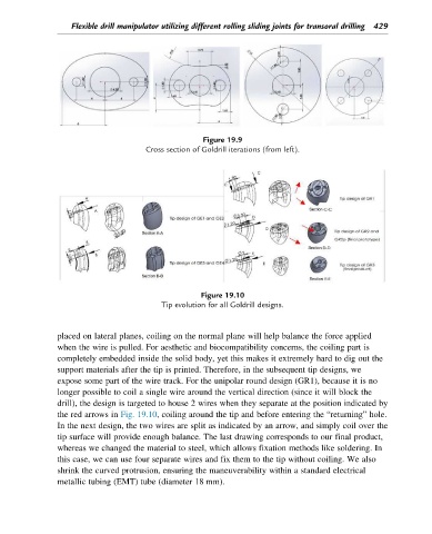
Cross section of Goldrill iterations (from left).
Figure 19.10
Tip evolution for all Goldrill designs.
placed on lateral planes, coiling on the normal plane will help balance the force applied
when the wire is pulled. For aesthetic and biocompatibility concerns, the coiling part is
completely embedded inside the solid body, yet this makes it extremely hard to dig out the
support materials after the tip is printed. Therefore, in the subsequent tip designs, we
expose some part of the wire track. For the unipolar round design (GR1), because it is no
longer possible to coil a single wire around the vertical direction (since it will block the
drill), the design is targeted to house 2 wires when they separate at the position indicated by
the red arrows in Fig. 19.10, coiling around the tip and before entering the “returning” hole.
In the next design, the two wires are split as indicated by an arrow, and simply coil over the
tip surface will provide enough balance. The last drawing corresponds to our final product,
whereas we changed the material to steel, which allows fixation methods like soldering. In
this case, we can use four separate wires and fix them to the tip without coiling. We also
shrink the curved protrusion, ensuring the maneuverability within a standard electrical
metallic tubing (EMT) tube (diameter 18 mm).