
Page 434 - Flexible Robotics in Medicine
P. 434
428 Chapter 19
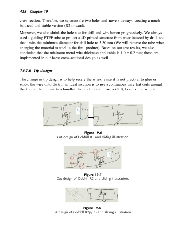
cross section. Therefore, we separate the two holes and move sideways, creating a much
balanced and stable version (R2 onward).
Moreover, we also shrink the hole size for drill and wire lumen progressively. We always
used a guiding PTFE tube to protect a 3D-printed structure from wear induced by drill, and
that limits the minimum diameter for drill hole to 3.30 mm (We will remove the tube when
changing the material to steel in the final product). Based on our test results, we also
concluded that the minimum metal wire thickness applicable is 1.0 6 0.2 mm; those are
implemented in our latest cross-sectional design as well.
19.3.6 Tip designs
The change in tip design is to help secure the wires. Since it is not practical to glue or
solder the wire onto the tip, an ideal solution is to use a continuous wire that coils around
the tip and then create two bundles. In the elliptical designs (GE), because the wire is
Figure 19.6
Cut design of Goldrill R1 and sliding illustration.
Figure 19.7
Cut design of Goldrill R2 and sliding illustration.
Figure 19.8
Cut design of Goldrill R2p/R3 and sliding illustration.