
Page 447 - Flexible Robotics in Medicine
P. 447
Flexible drill manipulator utilizing different rolling sliding joints for transoral drilling 441
medium wire does not deform over time, it serves as a suitable size for our prototype over
the long run.
19.6.1.3 Compression tests of polylactic acid material
We conducted a compression test on the drill head segment of our prototype, which is
the part that will experience the highest payload force during the surgery drilling
process. The drill head has shown to be able to withstand a large amount of force
( . 1000 N) without breaking. Only slight damage was observed at the top (Figs. 19.19
and 19.20).
19.6.2 Force and vibration tests with OptoForce
19.6.2.1 Segment bending
Although the American Society for Testing and Materials (ASTM) standard 3-point load
strength test was found, these were not suitable tests for our clinical purpose of measuring
the force exerted by the trachea. Furthermore, these tests do not apply for the segmented
design of the Goldrill GR3. Instead, a customized test using the OptoForce sensor was used.
The OptoForce is a sensor that measures the forces acting on the device in three
dimensions. This was used to determine the force required to unhinge the segments at any
point, which would constitute a loss in stability. This is analogous to the force generated by
pushing the drill bit against the trachea wall during drilling.
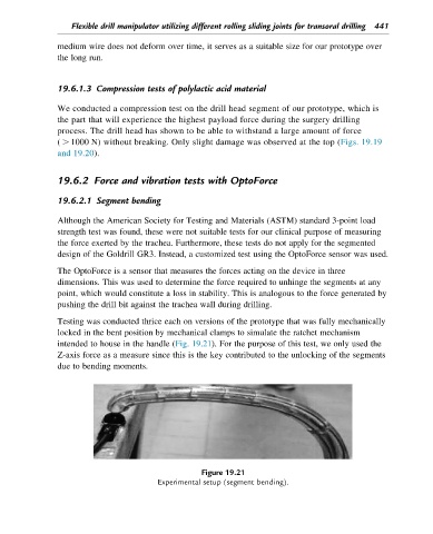
Testing was conducted thrice each on versions of the prototype that was fully mechanically
locked in the bent position by mechanical clamps to simulate the ratchet mechanism
intended to house in the handle (Fig. 19.21). For the purpose of this test, we only used the
Z-axis force as a measure since this is the key contributed to the unlocking of the segments
due to bending moments.
Figure 19.21
Experimental setup (segment bending).