
Page 158 - Fluid Mechanics and Thermodynamics of Turbomachinery
P. 158
Axial-flow Compressors and Fans 139
small compared with the mean radius. Again, as for axial turbines, the flow is
assumed to be invariant in the circumferential direction and that no spanwise (radial)
velocities occur. Some of the three-dimensional effects of axial turbomachines are
considered in Chapter 6.
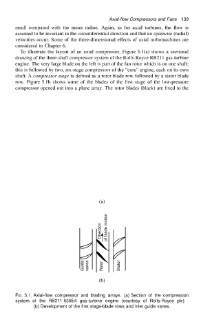
To illustrate the layout of an axial compressor, Figure 5.1(a) shows a sectional
drawing of the three-shaft compressor system of the Rolls-Royce RB211 gas-turbine
engine. The very large blade on the left is part of the fan rotor which is on one shaft;
this is followed by two, six-stage compressors of the “core” engine, each on its own
shaft. A compressor stage is defined as a rotor blade row followed by a stator blade
row. Figure 5.1b shows some of the blades of the first stage of the low-pressure
compressor opened out into a plane array. The rotor blades (black) are fixed to the
(a)
Direction of blade motion
Guide vanes Rotor Stator
(b)
FIG. 5.1. Axial-flow compressor and blading arrays. (a) Section of the compression
system of the RB211-535E4 gas-turbine engine (courtesy of Rolls-Royce plc).
(b) Development of the first stage-blade rows and inlet guide vanes.