
Page 159 - Fluid Mechanics and Thermodynamics of Turbomachinery
P. 159
140 Fluid Mechanics, Thermodynamics of Turbomachinery
rotor drum and the stator blades are fixed to the outer casing. The blades upstream
of the first rotor row are inlet guide vanes. These are not considered to be a part of
the first stage and are treated separately. Their function is quite different from the
other blade rows since, by directing the flow away from the axial direction, they act
to accelerate the flow rather than diffuse it. Functionally, inlet guide vanes are the
same as turbine nozzles; they increase the kinetic energy of the flow at the expense
of the pressure energy.
Velocity diagrams of the compressor stage
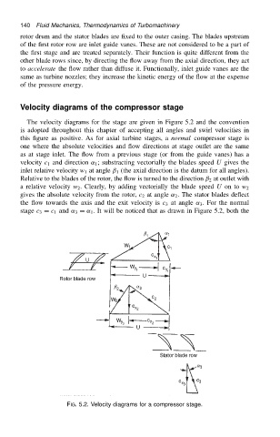
The velocity diagrams for the stage are given in Figure 5.2 and the convention
is adopted throughout this chapter of accepting all angles and swirl velocities in
this figure as positive. As for axial turbine stages, a normal compressor stage is
one where the absolute velocities and flow directions at stage outlet are the same
as at stage inlet. The flow from a previous stage (or from the guide vanes) has a
velocity c 1 and direction ˛ 1 ; substracting vectorially the blades speed U gives the
inlet relative velocity w 1 at angle ˇ 1 (the axial direction is the datum for all angles).
Relative to the blades of the rotor, the flow is turned to the direction ˇ 2 at outlet with
a relative velocity w 2 . Clearly, by adding vectorially the blade speed U on to w 2
gives the absolute velocity from the rotor, c 2 at angle ˛ 2 . The stator blades deflect
the flow towards the axis and the exit velocity is c 3 at angle ˛ 3 . For the normal
stage c 3 D c 1 and ˛ 3 D ˛ 1 . It will be noticed that as drawn in Figure 5.2, both the
FIG. 5.2. Velocity diagrams for a compressor stage.