Page 160 - Fluid Mechanics and Thermodynamics of Turbomachinery
P. 160

Axial-flow Compressors and Fans  141
                          relative velocity in the rotor and the absolute velocity in the stator are diffused. It
                          will be shown later in this chapter, that the relative amount of diffusion of kinetic
                          energy in the rotor and stator rows, significantly influences the stage efficiency.


                          Thermodynamics of the compressor stage

                            The specific work done by the rotor on the fluid, from the steady flow energy
                          equation (assuming adiabatic flow) and momentum equation is
                                                              c y1 /.                      (5.1)
                              W D P W p / Pm D h 02  h 01 D U.c y2
                                                                                          1
                                                                                            2
                          In Chapter 4 it was proved for all axial turbomachines that h 0rel D h C w is
                                                                                          2
                          constant in the rotor. Thus,
                                   1
                                     2
                                               2
                                             1
                              h 1 C w D h 2 C w .                                          (5.2)
                                   2  1      2  2
                          This is a valid result as long as there is no radial shift of the streamlines across the
                          rotor (i.e. U 1 D U 2 ).
                            Across the stator, h 0 is constant, and
                                   1 2
                                             1 2
                              h 2 C c D h 3 C c .                                          (5.3)
                                   2 2       2 3
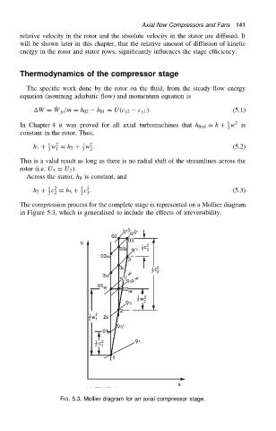
                          The compression process for the complete stage is represented on a Mollier diagram
                          in Figure 5.3, which is generalised to include the effects of irreversibility.


                                      FIG. 5.3. Mollier diagram for an axial compressor stage.
   155   156   157   158   159   160   161   162   163   164   165