
Page 197 - Fluid Mechanics and Thermodynamics of Turbomachinery
P. 197
178 Fluid Mechanics, Thermodynamics of Turbomachinery
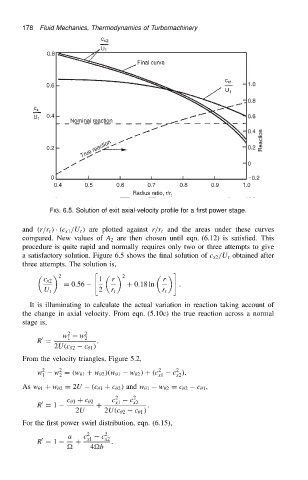
FIG. 6.5. Solution of exit axial-velocity profile for a first power stage.
and .r/r t / Ð .c x1 /U t / are plotted against r/r t and the areas under these curves
compared. New values of A 2 are then chosen until eqn. (6.12) is satisfied. This
procedure is quite rapid and normally requires only two or three attempts to give
a satisfactory solution. Figure 6.5 shows the final solution of c x2 /U t obtained after
three attempts. The solution is,
" #
2 2
c x2 1 r r
D 0.56 C 0.18 ln .
U t 2 r t r t
It is illuminating to calculate the actual variation in reaction taking account of
the change in axial velocity. From eqn. (5.10c) the true reaction across a normal
stage is,
w 1 2 w 2 2
0
R D .
2U.c 2 c 1 /
From the velocity triangles, Figure 5.2,
2
2
w 2 w D .w 1 C w 2 /.w 1 w 2 / C .c 2 c /.
1 2 x1 x2
As w 1 C w 2 D 2U .c 1 C c 2 / and w 1 w 2 D c 2 c 1 ,
c 2 c 2
0 c 1 C c 2 x1 x2
R D 1 C .
2U 2U.c 2 c 1 /
For the first power swirl distribution, eqn. (6.15),
a c 2 x1 c 2 x2
0
R D 1 C .
4b