
Page 201 - Fluid Mechanics and Thermodynamics of Turbomachinery
P. 201
182 Fluid Mechanics, Thermodynamics of Turbomachinery
which after logarithmic differentiation gives
dT/T D .
1/d / . (6.29)
Using the above set of equations the procedure for determining the nozzle exit
flow is as follows. Starting at r D r m , values of c m , ˛ m , T m and m are assumed to
be known. For a small finite interval r, the changes in velocity c, density ,
and temperature T can be computed using eqns. (6.27), (6.28) and (6.29) respec-
tively. Hence, at the new radius r D r m C r the velocity c D c m C c, the density
D m C and temperature T D T m C T are obtained. The corresponding flow
angle ˛ and Mach number M can now be determined from eqns. (6.26) and (6.28a)
respectively. Thus, all parameters of the problem are known at radius r D r m C r.
This procedure is repeated for further increments in radius to the casing and again
from the mean radius to the hub.
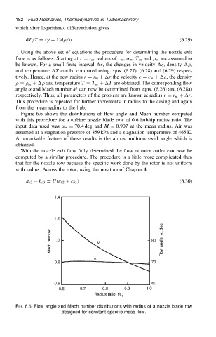
Figure 6.6 shows the distributions of flow angle and Mach number computed
with this procedure for a turbine nozzle blade row of 0.6 hub/tip radius ratio. The
input data used was ˛ m D 70.4 deg and M D 0.907 at the mean radius. Air was
assumed at a stagnation pressure of 859 kPa and a stagnation temperature of 465 K.
A remarkable feature of these results is the almost uniform swirl angle which is
obtained.
With the nozzle exit flow fully determined the flow at rotor outlet can now be
computed by a similar procedure. The procedure is a little more complicated than
that for the nozzle row because the specific work done by the rotor is not uniform
with radius. Across the rotor, using the notation of Chapter 4,
h o2 h o3 D U.c 2 C c 3 / (6.30)
FIG. 6.6. Flow angle and Mach number distributions with radius of a nozzle blade row
designed for constant specific mass flow.