Page 205 - Fluid Mechanics and Thermodynamics of Turbomachinery
P. 205

186 Fluid Mechanics, Thermodynamics of Turbomachinery


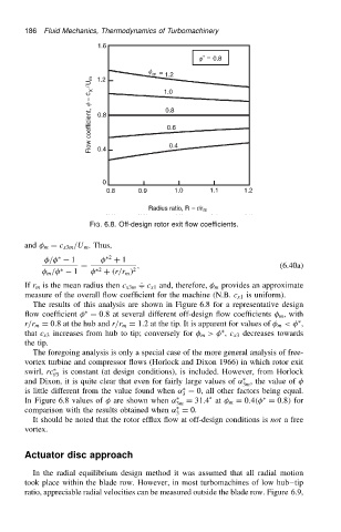
                                          FIG. 6.8. Off-design rotor exit flow coefficients.

                          and   m D c x3m /U m . Thus,

                                /   Ł  1       Ł2  C 1
                                        D             ,                                  (6.40a)
                                m /  Ł  1    Ł2  C .r/r m / 2
                          If r m is the mean radius then c x3m + c x1 and, therefore,   m provides an approximate
                          measure of the overall flow coefficient for the machine (N.B. c x1 is uniform).
                            The results of this analysis are shown in Figure 6.8 for a representative design
                                         Ł
                          flow coefficient   D 0.8 at several different off-design flow coefficients   m , with
                                                                                              Ł
                          r/r m D 0.8 at the hub and r/r m D 1.2 at the tip. It is apparent for values of   m <  ,
                                                                           Ł
                          that c x3 increases from hub to tip; conversely for   m >  , c x3 decreases towards
                          the tip.
                            The foregoing analysis is only a special case of the more general analysis of free-
                          vortex turbine and compressor flows (Horlock and Dixon 1966) in which rotor exit
                          swirl, rc Ł  is constant (at design conditions), is included. However, from Horlock
                                  3
                                                                                Ł
                          and Dixon, it is quite clear that even for fairly large values of ˛ , the value of
                                                                                3m
                                                                 Ł
                          is little different from the value found when ˛ D 0, all other factors being equal.
                                                                 3
                                                                                     Ł
                          In Figure 6.8 values of   are shown when ˛ Ł  D 31.4 ° at   m D 0.4.  D 0.8/ for
                                                                3m
                                                                Ł
                          comparison with the results obtained when ˛ D 0.
                                                                3
                            It should be noted that the rotor efflux flow at off-design conditions is not a free
                          vortex.
                          Actuator disc approach
                            In the radial equilibrium design method it was assumed that all radial motion
                          took place within the blade row. However, in most turbomachines of low hub tip
                          ratio, appreciable radial velocities can be measured outside the blade row. Figure 6.9,
   200   201   202   203   204   205   206   207   208   209   210