
Page 208 - Fluid Mechanics and Thermodynamics of Turbomachinery
P. 208
Three-dimensional Flows in Axial Turbomachines 189
FIG. 6.11. The actuator disc assumption (after Horlock 1958).
An isolated actuator disc is depicted in Figure 6.11 with radial equilibrium estab-
lished at fairly large axial distances from the disc. An approximate solution to the
velocity fields upstream and downstream of the actuator can be found in terms
of the axial velocity distributions, far upstream and far downstream of the disc.
The detailed analysis exceeds the scope of this book, involving the solution of the
equations of motion, the equation of continuity and the satisfaction of boundary
conditions at the walls and disc. The form of the approximate solution is of consid-
erable interest and is quoted below.
For convenience, conditions far upstream and far downstream of the disc are
denoted by subscripts 11 and 12 respectively (Figure 6.11). Actuator disc theory
proves that at the disc (x D 0), at any given radius, the axial velocity is equal to the
mean of the axial velocities at 11 and 12 at the same radius, or
1
c x01 D c x02 D .c x11 C c x12 /. (6.41)
2
Subscripts 01 and 02 denote positions immediately upstream and downstream
respectively of the actuator disc. Equation (6.41) is known as the mean-value rule.
In the downstream flow field .x = 0/, the difference in axial velocity at some
position (x, r A ) to that at position .x D1,r A / is conceived as a velocity perturbation.
Referring to Figure 6.12, the axial velocity perturbation at the disc .x D 0,r A / is
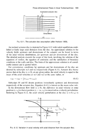
FIG. 6.12. Variation in axial velocity with axial distance from the actuator disc.