
Page 213 - Fluid Mechanics and Thermodynamics of Turbomachinery
P. 213
194 Fluid Mechanics, Thermodynamics of Turbomachinery
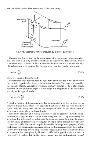
FIG. 6.15. Secondary vorticity produced by a row of guide vanes.
Consider the flow at inlet to the guide vanes of a compressor to be completely
axial and with a velocity profile as illustrated in Figure 6.15. This velocity profile
is non-uniform as a result of friction between the fluid and the wall; the vorticity
of this boundary layer is normal to the approach velocity c 1 and of magnitude
dc 1
ω 1 D , (6.51)
dz
where z is distance from the wall.
The direction of ω 1 follows from the right-hand screw rule and it will be observed
that ω 1 is in opposite directions on the two annulus walls. This vector is turned by
the cascade, thereby generating secondary vorticity parallel to the outlet stream
direction. If the deflection angle is not large, the magnitude of the secondary
vorticity ω s is, approximately,
dc 1
ω s D2 . (6.52)
dz
A swirling motion of the cascade exit flow is associated with the vorticity ω s ,as
shown in Figure 6.16, which is in opposite directions for the two wall boundary
layers. This secondary flow will be the integrated effect of the distribution of
secondary vorticity along the blade length.
Now if the variation of c 1 with z is known or can be predicted, then the distri-
bution of ω s along the blade can be found using eqn. (6.52). By considering the
secondary flow to be small perturbation of the two-dimensional flow from the vanes,
the flow angle distribution can be calculated using a series solution developed by
Hawthorne (1955). The actual analysis lies outside the scope (and purpose) of this
book, however. Experiments on cascade show excellent agreement with these calcu-
lations provided there are but small viscous effects and no flow separations. Such
a comparison has been given by Horlock (1963) and a typical result is shown in
Figure 6.17. It is clear that the flow is overturned near the walls and underturned