
Page 257 - Fluid Mechanics and Thermodynamics of Turbomachinery
P. 257
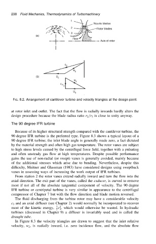
238 Fluid Mechanics, Thermodynamics of Turbomachinery


                           FIG. 8.2. Arrangement of cantilever turbine and velocity triangles at the design point.


                          at rotor inlet and outlet. The fact that the flow is radially inwards hardly alters the
                          design procedure because the blade radius ratio r 2 /r 3 is close to unity anyway.

                          The 90 degree IFR turbine

                            Because of its higher structural strength compared with the cantilever turbine, the
                          90 degree IFR turbine is the preferred type. Figure 8.3 shows a typical layout of a
                          90 degree IFR turbine; the inlet blade angle is generally made zero, a fact dictated
                          by the material strength and often high gas temperature. The rotor vanes are subject
                          to high stress levels caused by the centrifugal force field, together with a pulsating
                          and often unsteady gas flow at high temperatures. Despite possible performance
                          gains the use of non-radial (or swept) vanes is generally avoided, mainly because
                          of the additional stresses which arise due to bending. Nevertheless, despite this
                          difficulty, Meitner and Glassman (1983) have considered designs using sweptback
                          vanes in assessing ways of increasing the work output of IFR turbines.
                            From station 2 the rotor vanes extend radially inward and turn the flow into the
                          axial direction. The exit part of the vanes, called the exducer, is curved to remove
                          most if not all of the absolute tangential component of velocity. The 90 degree
                          IFR turbine or centripetal turbine is very similar in appearance to the centrifugal
                          compressor of Chapter 7 but with the flow direction and blade motion reversed.
                            The fluid discharging from the turbine rotor may have a considerable velocity
                          c 3 and an axial diffuser (see Chapter 2) would normally be incorporated to recover
                                                   c , which would otherwise be wasted. In hydraulic
                          most of the kinetic energy,  1 2
                                                  2 3
                          turbines (discussed in Chapter 9) a diffuser is invariably used and is called the
                          draught tube.
                            In Figure 8.3 the velocity triangles are drawn to suggest that the inlet relative
                          velocity, w 2 ,is radially inward, i.e. zero incidence flow, and the absolute flow