
Page 259 - Fluid Mechanics and Thermodynamics of Turbomachinery
P. 259
240 Fluid Mechanics, Thermodynamics of Turbomachinery
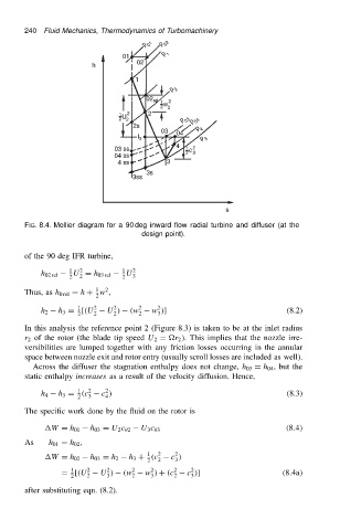
FIG. 8.4. Mollier diagram for a 90 deg inward flow radial turbine and diffuser (at the
design point).
of the 90 deg IFR turbine,
1 2 1 2
h 02 rel U D h 03 rel U 3
2
2 2
2
1
Thus, as h 0 rel D h C w ,
2
1
2
2
h 3 D [.U 2 U / .w 2 w /] (8.2)
h 2 2 2 2 3
2
In this analysis the reference point 2 (Figure 8.3) is taken to be at the inlet radius
r 2 of the rotor (the blade tip speed U 2 D r 2 /. This implies that the nozzle irre-
versibilities are lumped together with any friction losses occurring in the annular
space between nozzle exit and rotor entry (usually scroll losses are included as well).
Across the diffuser the stagnation enthalpy does not change, h 03 D h 04 , but the
static enthalpy increases as a result of the velocity diffusion. Hence,
2
1
h 4 h 3 D .c 2 3 c / (8.3)
4
2
The specific work done by the fluid on the rotor is
W D h 01 h 03 D U 2 c 2 U 3 c 3 .8.4/
As h 01 D h 02 ,
2
1
h 3 C .c 2 c /
W D h 02 h 03 D h 2 2 3
2
2
2
2
1
D [.U 2 U / .w 2 w / C .c 2 c /] .8.4a/
2 2 3 2 3 2 3
after substituting eqn. (8.2).