Page 264 - Fluid Mechanics and Thermodynamics of Turbomachinery
P. 264

Radial Flow Gas Turbines  245
                                            p
                          rotor speed N D 2410 400 D 48 200 rev/min, the rotor tip speed U 2 D  ND 2 /60 D
                                                                                  2
                          183 m/s and hence the specific work done by the rotor W D U D 33.48 kJ/kg.
                                                                                  2
                          The corresponding isentropic total-to-static enthalpy drop is
                              h 01  h 3ss D C p T 01 [1  .p 3 /p 01 / .
 1//
 ]
                                       D 1.005 ð 400[1  .1/1.5/ 1/3.5 ] D 43.97 kJ/kg

                          Thus, the total-to-static efficiency is

                                ts D W/.h 01  h 3ss / D 76.14%
                            The actual specific work output to the shaft, after allowing for the bearing friction
                          loss, is


                                                      N      p 01
                              W act D  / Pm D      p       p        T 01
                                               p 01   T 01  P m T 01  30
                                                                                5
                                    D 4.59 ð 10  6  ð 2410 ð   ð 400/.30 ð 1.44 ð 10 /
                                    D 32.18 kJ/kg

                          Thus, the turbine overall total-to-static efficiency is

                                0 D W act /.h 01  h 3ss / D 73.18%

                            By rearranging eqn. (8.9a) the rotor enthalpy loss coefficient can be obtained:
                                                                     2
                                                                  2
                                                                               2
                                                       2
                                R Df2.1/  ts  1/    N cosec ˛ 2 g.r 2 /r 3av / sin ˇ 3av  cos ˇ 3av
                                Df2.1/0.7613   1/  0.065 ð 1.1186gð 4.442 ð 0.6378
                                    0.3622
                                D 1.208

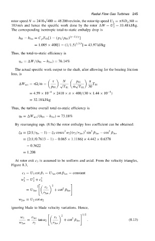
                            At rotor exit c 3 is assumed to be uniform and axial. From the velocity triangles,
                          Figure 8.3,
                                c 3 D U 3 cot ˇ 3 D U 3av cot ˇ 3av D constant
                                 2
                                      2
                               w D U C c  2
                                 3    3   3
                                        "                 #
                                        2        2
                                            r 3
                                                      2
                                  D U 3av        C cot ˇ 3av
                                           r 3av
                              w 2av D U 2 cot ˛ 2
                          ignoring blade to blade velocity variations. Hence,
                                              "                 # 1/2
                                                      2
                               w 3   r 3av       r 3       2
                                   D    tan ˛ 2        C cot ˇ 3av  .                     (8.13)
                              w 2av   r 2        r 3av
   259   260   261   262   263   264   265   266   267   268   269