
Page 268 - Fluid Mechanics and Thermodynamics of Turbomachinery
P. 268
Radial Flow Gas Turbines 249
P S P S
Direction
of rotation
(a)
a 2
b 2
c 2
w 2
U 2
(b)
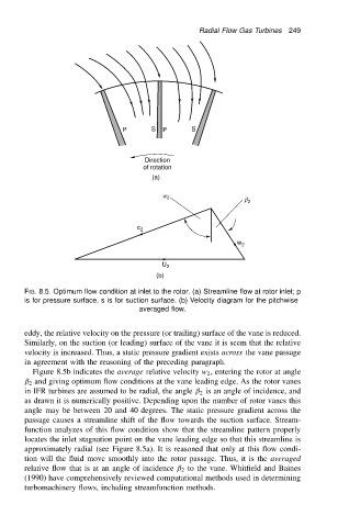
FIG. 8.5. Optimum flow condition at inlet to the rotor. (a) Streamline flow at rotor inlet; p
is for pressure surface, s is for suction surface. (b) Velocity diagram for the pitchwise
averaged flow.
eddy, the relative velocity on the pressure (or trailing) surface of the vane is reduced.
Similarly, on the suction (or leading) surface of the vane it is seem that the relative
velocity is increased. Thus, a static pressure gradient exists across the vane passage
in agreement with the reasoning of the preceding paragraph.
Figure 8.5b indicates the average relative velocity w 2 , entering the rotor at angle
ˇ 2 and giving optimum flow conditions at the vane leading edge. As the rotor vanes
in IFR turbines are assumed to be radial, the angle ˇ 2 is an angle of incidence, and
as drawn it is numerically positive. Depending upon the number of rotor vanes this
angle may be between 20 and 40 degrees. The static pressure gradient across the
passage causes a streamline shift of the flow towards the suction surface. Stream-
function analyzes of this flow condition show that the streamline pattern properly
locates the inlet stagnation point on the vane leading edge so that this streamline is
approximately radial (see Figure 8.5a). It is reasoned that only at this flow condi-
tion will the fluid move smoothly into the rotor passage. Thus, it is the averaged
relative flow that is at an angle of incidence ˇ 2 to the vane. Whitfield and Baines
(1990) have comprehensively reviewed computational methods used in determining
turbomachinery flows, including streamfunction methods.