Page 271 - Fluid Mechanics and Thermodynamics of Turbomachinery
P. 271

252 Fluid Mechanics, Thermodynamics of Turbomachinery
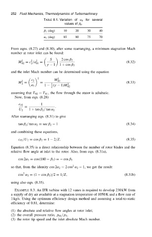
                                            TABLE 8.1. Variation of ˛ 2 for several
                                                        values of ˇ 2 .
                                            ˇ 2 (deg)  10     20    30     40
                                            ˛ 2 (deg)  85     80    75     70


                          From eqns. (8.27) and (8.30), after some rearranging, a minimum stagnation Mach
                          number at rotor inlet can be found:

                                                S
                                2    2  2             2 cos ˇ 2
                              M 02  D c /a 01  D                                          (8.32)
                                     2
                                              
   1  1 C cos ˇ 2
                          and the inlet Mach number can be determined using the equation
                                         2        M 2
                                2
                              M D    c 2  D         02                                    (8.33)
                                2               1        2
                                     a 2    1    .
   1/M
                                                2        02
                          assuming that T 02 D T 01 , the flow through the stator is adiabatic.
                            Now, from eqn. (8.28)
                              c  2         1
                                 D                .
                              U 2   1 C tan ˇ 2 / tan ˛ 2
                          After rearranging eqn. (8.31) to give
                                                   1                                      (8.34)
                              tan ˇ 2 / tan ˛ 2 D sec ˇ 2
                          and combining these equations,

                              c  2 /U 2 D cos ˇ 2 D 1  2/Z.                               (8.35)
                          Equation (8.35) is a direct relationship between the number of rotor blades and the
                          relative flow angle at inlet to the rotor. Also, from eqn. (8.31a),

                              cos 2˛ 2 D cos.180  ˇ 2 / D cos ˇ 2
                                                            2
                          so that, from the identity cos 2˛ 2 D 2 cos ˛ 2  1, we get the result:
                                 2
                              cos ˛ 2 D .1  cos ˇ 2 //2 D 1/Z,                           (8.31b)
                          using also eqn. (8.35).
                            EXAMPLE 8.3. An IFR turbine with 12 vanes is required to develop 230 kW from
                          a supply of dry air available at a stagnation temperature of 1050 K and a flow rate of
                          1 kg/s. Using the optimum efficiency design method and assuming a total-to-static
                          efficiency of 0.81, determine:
                          (1) the absolute and relative flow angles at rotor inlet;
                          (2) the overall pressure ratio, p 01 /p 3 ,
                          (3) the rotor tip speed and the inlet absolute Mach number.
   266   267   268   269   270   271   272   273   274   275   276