
Page 276 - Fluid Mechanics and Thermodynamics of Turbomachinery
P. 276
Radial Flow Gas Turbines 257
rotor tip radius ratio, r 3s /r 2 , and the exit hub to shroud radius ratio, D r 3h /r 3s , all
have to be considered. It is assumed that the absolute flow at rotor exit is entirely
axial so that the relative velocity can be written:
2
2
w D c 2 C U .
3 m3 3
If values of c m3 /U 2 and r 3av /r 2 can be chosen, then the exit flow angle variation
can be found for all radii. From the rotor exit velocity diagram in Figure 8.3,
c m3 r 3av r 3
D cot ˇ 3av D cot ˇ 3 . (8.45)
U 2 r 2 r 2
The meridional velocity c m3 should be kept small in order to minimise the exhaust
energy loss, unless an exhaust diffuser is fitted to the turbine.
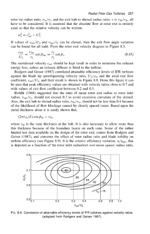
Rodgers and Geiser (1987) correlated attainable efficiency levels of IFR turbines
against the blade tip speed/spouting velocity ratio, U 2 /c 0 , and the axial exit flow
coefficient, c m3 /U 2 , and their result is shown in Figure 8.8. From this figure it can
be seen that peak efficiency values are obtained with velocity ratios close to 0.7 and
with values of exit flow coefficient between 0.2 and 0.3.
Rohlik (1968) suggested that the ratio of mean rotor exit radius to rotor inlet
radius, r 3av /r 2 , should not exceed 0.7 to avoid excessive curvature of the shroud.
Also, the exit hub to shroud radius ratio, r 3h /r 3s , should not be less than 0.4 because
of the likelihood of flow blockage caused by closely spaced vanes. Based upon the
metal thickness alone it is easily shown that,
.2 r 3h /Z/ cos ˇ 3h >t 3h ,
where t 3h is the vane thickness at the hub. It is also necessary to allow more than
this thickness because of the boundary layers on each vane. Some of the rather
limited test data available on the design of the rotor exit, comes from Rodgers and
Geiser (1987), and concerns the effect of rotor radius ratio and blade solidity on
turbine efficiency (see Figure 8.9). It is the relative efficiency variation, / opt , that
is depicted as a function of the rotor inlet radius/exit root mean square radius ratio,
0.8
0.7 88
U 2 /c o 86 84
82 80
0.6
= 78
h ts
0.5
0.1 0.2 0.3 0.4 0.6 0.8 1.0
c m3 /U 2
FIG. 8.8. Correlation of attainable efficiency levels of IFR turbines against velocity ratios
(adapted from Rodgers and Geiser 1987).