Page 277 - Fluid Mechanics and Thermodynamics of Turbomachinery
P. 277

258 Fluid Mechanics, Thermodynamics of Turbomachinery
                                   1.1


                                   1.0

                                  h/h opt


                                                                               ZL/D 2
                                   0.9
                                                                               6.0
                                                             3.0     4.0 4.5 5.0


                                   0.8
                                      1.5            2.0             2.5             3.0
                                                            r /r
                                                             2 3rms
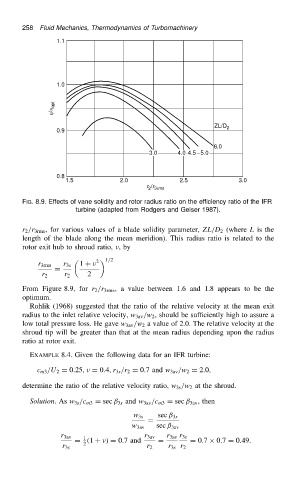
                          FIG. 8.9. Effects of vane solidity and rotor radius ratio on the efficiency ratio of the IFR
                                         turbine (adapted from Rodgers and Geiser 1987).


                          r 2 /r 3rms , for various values of a blade solidity parameter, ZL/D 2 (where L is the
                          length of the blade along the mean meridion). This radius ratio is related to the
                          rotor exit hub to shroud ratio,  ,by
                                              2    1/2
                              r 3rms  r 3s  1 C
                                   D
                               r 2   r 2    2
                          From Figure 8.9, for r 2 /r 3rms , a value between 1.6 and 1.8 appears to be the
                          optimum.
                            Rohlik (1968) suggested that the ratio of the relative velocity at the mean exit
                          radius to the inlet relative velocity, w 3av /w 2 , should be sufficiently high to assure a
                          low total pressure loss. He gave w 3av /w 2 a value of 2.0. The relative velocity at the
                          shroud tip will be greater than that at the mean radius depending upon the radius
                          ratio at rotor exit.
                            EXAMPLE 8.4. Given the following data for an IFR turbine:

                              c m3 /U 2 D 0.25,  D 0.4,r 3s /r 2 D 0.7 and w 3av /w 2 D 2.0,

                          determine the ratio of the relative velocity ratio, w 3s /w 2 at the shroud.
                            Solution.As w 3s /c m3 D sec ˇ 3s and w 3av /c m3 D sec ˇ 3av , then

                                                        w 3s   sec ˇ 3s
                                                            D
                                                        w 3av  sec ˇ 3av
                                    r 3av  1               r 3av  r 3av r 3s
                                        D .1 C v/ D 0.7 and    D        D 0.7 ð 0.7 D 0.49.
                                           2
                                     r 3s                   r 2   r 3s r 2
   272   273   274   275   276   277   278   279   280   281   282