Page 280 - Fluid Mechanics and Thermodynamics of Turbomachinery
P. 280

Radial Flow Gas Turbines  261
                                                                   P 01
                                                  h
                                                                     P 1
                                                         01
                                                                                 P 02 ¢ rel
                                                         1
                                                                  02¢rel           P 02rel
                                                                                 02rel

                               (1)        b 2 ¢                                 P 2

                                          w 2 ¢
                                                                         2
                                                                  2¢
                                                        2s


                              (2)                                                 P 3
                                         b 2, opt                              3
                                                                                            (b)
                                                                        3s
                               w 2
                                                                 3s¢
                                                          3ss
                            (a)

                                                                                           s

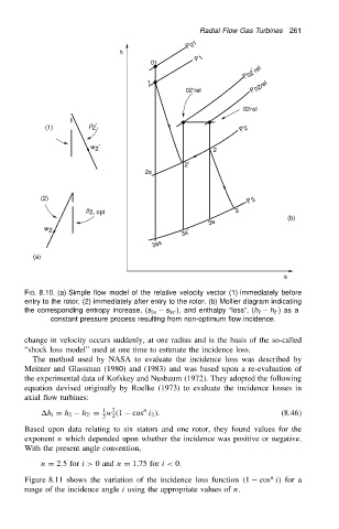
                          FIG. 8.10. (a) Simple flow model of the relative velocity vector (1) immediately before
                          entry to the rotor, (2) immediately after entry to the rotor. (b) Mollier diagram indicating
                                                                                       h 2 0)asa
                          the corresponding entropy increase, (s 3s  s 3s 0), and enthalpy “loss”, (h 2
                                constant pressure process resulting from non-optimum flow incidence.
                          change in velocity occurs suddenly, at one radius and is the basis of the so-called
                          “shock loss model” used at one time to estimate the incidence loss.
                            The method used by NASA to evaluate the incidence loss was described by
                          Meitner and Glassman (1980) and (1983) and was based upon a re-evaluation of
                          the experimental data of Kofskey and Nusbaum (1972). They adopted the following
                          equation devised originally by Roelke (1973) to evaluate the incidence losses in
                          axial flow turbines:
                                             1
                                                2
                                                        n
                              h i D h 2  h 2 D w .1  cos i 2 /.                          (8.46/
                                          0
                                             2  2
                          Based upon data relating to six stators and one rotor, they found values for the
                          exponent n which depended upon whether the incidence was positive or negative.
                          With the present angle convention,
                              n D 2.5 for i> 0 and n D 1.75 for i< 0.
                                                                                       n
                          Figure 8.11 shows the variation of the incidence loss function .1  cos i/ for a
                          range of the incidence angle i using the appropriate values of n.
   275   276   277   278   279   280   281   282   283   284   285