
Page 283 - Fluid Mechanics and Thermodynamics of Turbomachinery
P. 283
264 Fluid Mechanics, Thermodynamics of Turbomachinery
1 2
For the 90 deg IFR turbine, writing U 2 D ND 2 and h 0s D c , eqn. (8.47) can
2 0
be factorised as follows:
1/2 1/2
Q 3 U 2 U 2
N s D
1 2 3/4
. c / D 2 ND 2
2 0
p !
3/2 3/2 1/2
2 U 2 Q 3
D 3 .8.48/
c 0 ND
2
For the ideal 90 deg. IFR turbine and with c 02 D U 2 , it was shown earlier that the
p
blade speed to spouting velocity ratio, U 2 /c 0 D 1/ 2 D 0.707. Substituting this
value into eqn. (8.34),
1/2
Q 3
N s D 0.18 3 , .rev/ (8.48a/
ND
2
i.e. specific speed is directly proportional to the square root of the volumetric flow
coefficient.
To obtain some physical significance from eqns. (8.47) and (8.48a), define a
2
rotor disc area A d D D /4 and assume a uniform axial rotor exit velocity c 3 so
2
that Q 3 D A 3 c 3 , then as
p
c 0 2
N D U 2 /. D 2 / D
2 D 2
A 3 c 3 2
Q 3 A 3 c 3 2 D 2
D p D p
ND 3 2c 0 D 2 A d c 0 2 2
2 2
Hence,
1/2 1/2
c 3 A 3
N s D 0.336 , .rev/ (8.48b)
c 0 A d
or,
1/2 1/2
c 3 A 3
s D 2.11 , .rad/ (8.48c)
c 0 A d
In an early study of IFR turbine design for maximum efficiency, Rohlik (1968)
specified that the ratio of the rotor shroud diameter to rotor inlet diameter should be
limited to a maximum value of 0.7 to avoid excessive shroud curvature and that the
exit hub to shroud tip ratio was limited to a minimum of 0.4 to avoid excess hub
blade blockage and loss. Using this as data, an upper limit for A 3 /A d can be found,
" #
2 2
A 3 D 3s D 3h 2
D 1 D 0.7 ð .1 0.16/ D 0.41.
A d D 2 D 3s
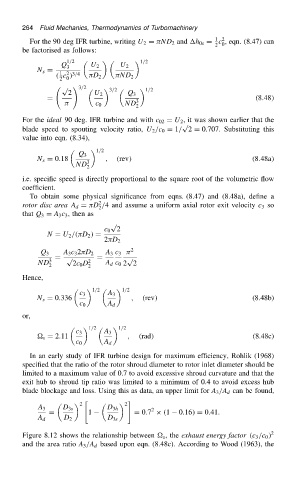
Figure 8.12 shows the relationship between s , the exhaust energy factor .c 3 /c 0 / 2
and the area ratio A 3 /A d based upon eqn. (8.48c). According to Wood (1963), the