
Page 266 - Fluid Mechanics and Thermodynamics of Turbomachinery
P. 266
Radial Flow Gas Turbines 247
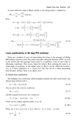
At rotor outlet the relative Mach number at the design point is defined by,
w 3 r 3 U 2
M r3 D D cosec ˇ 3 .
a 3 r 2 a 3
Now,
2 1 2 2 1 2 2
h 3 D h 01 .U C c / D h 01 .U C U cot ˇ 3 /
2 2 3 2 2 3
" #
2
2 1 r 3
D h 01 U 2 1 C 2 cot ˇ 3
r 2
" #
2
2
a D a 2 .
1/U 2 1 C 1 r 3
3 01 2 2 cot ˇ 3
r 2
.U 2 /a 01 /.r 3 /r 2 /
∴ M r3 D .8.15/
" ( )# 1/2
2
sin ˇ 3 1 .
1/.U 2 /a 01 / 2 1 C 1 r 3 cot ˇ 3
2
r 2
Loss coefficients in 90 deg IFR turbines
There are a number of ways of representing the losses in the passages of 90 deg
IFR turbines and these have been listed and inter-related by Benson (1970). As well
as the nozzle and rotor passage losses there is, in addition, a loss at rotor entry at
off-design conditions. This occurs when the relative flow entering the rotor is at
some angle of incidence to the radial vanes so that it can be called an incidence
loss. It is often referred to as a “shock loss” but this can be a rather misleading
term because, usually, there is no shock wave.
(i) Nozzle loss coefficients
The enthalpy loss coefficient, which normally includes the inlet scroll losses, has
already been defined and is,
1 2
N D .h 2 h 2s //. c /. (8.16)
2 2
Also in use is the velocity coefficient,
(8.17)
N D c 2 /c 2s
and the stagnation pressure loss coefficient,
Y N D .p 01 p 02 //.p 02 p 2 / (8.18a)
which can be related, approximately, to N by
1
2
Y N ' N .1 C
M / (8.18b)
2 2
1 2 1 2 1 2 2
Since, h 01 D h 2 C c D h 2s C c , then h 2 h 2s D .c 2s c / and
2
2 2 2 2s 2
1
N D 1. (8.19)
2
N