
Page 258 - Fluid Mechanics and Thermodynamics of Turbomachinery
P. 258
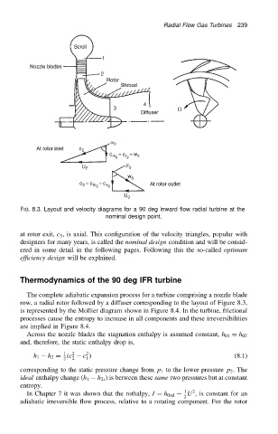
Radial Flow Gas Turbines  239


                          FIG. 8.3. Layout and velocity diagrams for a 90 deg inward flow radial turbine at the
                                                    nominal design point.


                          at rotor exit, c 3 , is axial. This configuration of the velocity triangles, popular with
                          designers for many years, is called the nominal design condition and will be consid-
                          ered in some detail in the following pages. Following this the so-called optimum
                          efficiency design will be explained.


                          Thermodynamics of the 90 deg IFR turbine

                            The complete adiabatic expansion process for a turbine comprising a nozzle blade
                          row, a radial rotor followed by a diffuser corresponding to the layout of Figure 8.3,
                          is represented by the Mollier diagram shown in Figure 8.4. In the turbine, frictional
                          processes cause the entropy to increase in all components and these irreversibilities
                          are implied in Figure 8.4.
                            Across the nozzle blades the stagnation enthalpy is assumed constant, h 01 D h 02
                          and, therefore, the static enthalpy drop is,
                                              2
                                       1
                              h 1  h 2 D .c 2 2  c /                                       (8.1)
                                              1
                                       2
                          corresponding to the static pressure change from p 1 to the lower pressure p 2 . The
                          ideal enthalpy change (h 1  h 2s ) is between these same two pressures but at constant
                          entropy.
                                                                            1  2
                            In Chapter 7 it was shown that the rothalpy, I D h 0rel  U , is constant for an
                                                                            2
                          adiabatic irreversible flow process, relative to a rotating component. For the rotor