
Page 290 - Fluid Mechanics and Thermodynamics of Turbomachinery
P. 290
Radial Flow Gas Turbines 271
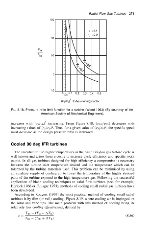
FIG. 8.18. Pressure ratio limit function for a turbine (Wood 1963) (By courtesy of the
American Society of Mechanical Engineers).
2
increases with .c 3 /c 0 / increasing. From Figure 8.18, .p 01 /p 03 / decreases with
2
2
increasing values of .c 3 /c 0 / . Thus, for a given value of .c 3 /c 0 / , the specific speed
must decrease as the design pressure ratio is increased.
Cooled 90 deg IFR turbines
The incentive to use higher temperatures in the basic Brayton gas turbine cycle is
well known and arises from a desire to increase cycle efficiency and specific work
output. In all gas turbines designed for high efficiency a compromise is necessary
between the turbine inlet temperature desired and the temperature which can be
tolerated by the turbine materials used. This problem can be minimised by using
an auxiliary supply of cooling air to lower the temperature of the highly stressed
parts of the turbine exposed to the high temperature gas. Following the successful
application of blade cooling techniques to axial flow turbines (see, for example,
Horlock 1966 or Fullagar 1973), methods of cooling small radial gas turbines have
been developed.
According to Rodgers (1969) the most practical method of cooling small radial
turbines is by film (or veil) cooling, Figure 8.19, where cooling air is impinged on
the rotor and vane tips. The main problem with this method of cooling being its
relatively low cooling effectiveness, defined by
T 01 .T m C T 0 /
ε D (8.56)
T 01 .T 0c C T 0 /