
Page 298 - Fluid Mechanics and Thermodynamics of Turbomachinery
P. 298
Hydraulic Turbines 279
The American engineer James B. Francis designed the first radial-inflow hydraulic
turbine which became widely used, gave excellent results and was highly regarded.
In its original form it was used for heads of between 10 and 100 m. A simplified
form of this turbine is shown in Figure 1.1d. It will be observed that the flow path
followed is essentially from a radial direction to an axial direction.
The Pelton wheel turbine, named after its American inventor Lester A. Pelton, was
brought into use in the second half of the nineteenth century. This is an impulse
turbine in which water is piped at high pressure to a nozzle where it expands
completely to atmospheric pressure. The emerging jet impacts onto the blades (or
buckets) of the turbine producing the required torque and power output. A simplified
diagram of a Pelton wheel turbine is shown in Figure 1.1f. The head of water used
originally was between about 90 m and 900 m (modern versions operate up to heads
of 2000 m).
The increasing need for more power during the early years of the twentieth century
also led to the invention of a turbine suitable for small heads of water, i.e. 3 m to
9 m, in river locations where a dam could be built. It was in 1913 that Viktor Kaplan
revealed his idea of the propeller (or Kaplan) turbine, see Figure 1.1e, which acts
like a ship’s propeller but in reverse At a later date Kaplan improved his turbine
by means of swivelable blades which improved the efficiency of the turbine in
accordance with the prevailing conditions (i.e. the available flow rate and head).
Flow regimes for maximum efficiency
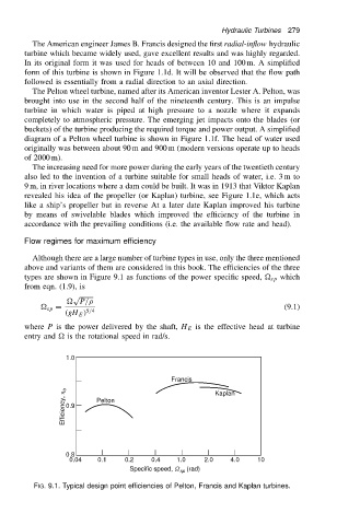
Although there are a large number of turbine types in use, only the three mentioned
above and variants of them are considered in this book. The efficiencies of the three
types are shown in Figure 9.1 as functions of the power specific speed, sp which
from eqn. (1.9), is
p
P/
sp D (9.1)
.gH E / 5/4
where P is the power delivered by the shaft, H E is the effective head at turbine
entry and is the rotational speed in rad/s.
1.0
Francis Kaplan
Efficiency, h o 0.9 Pelton
0.8
0.04 0.1 0.2 0.4 1.0 2.0 4.0 10
Specific speed, W (rad)
sp
FIG. 9.1. Typical design point efficiencies of Pelton, Francis and Kaplan turbines.